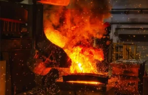
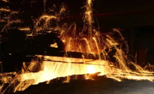
Induction furnaces are notorious “مثيري الشغب” in industrial power grids. As typical non-linear loads, balancing melting efficiency with grid “صحة” is a constant battle for electrical engineers and facility managers.
Equipment Interference & Invisible Losses
Core Pain Point: Why is the transformer overheating even when not fully loaded? Why do the CNC machines in the adjacent workshop alarm for no apparent reason?
Mechanism of Harmonic Generation
The core of an induction furnace power supply lies in the تصحيح (AC to DC) و الانقلاب (DC to AC) stages. When high-power Thyristors (SCR) or IGBTs perform high-frequency switching, the current waveform distorts. It ceases to be a standard sine wave, generating high-order harmonics (primarily 5th, 7th, 11th, and 13th orders).
The Damage Caused
- Transformer Overheating: High-frequency harmonic currents cause severe تأثير الجلد in conductors, increasing winding resistance losses; they also increase hysteresis and eddy current losses in the iron core.
- Capacitor Explosions: If the factory’s compensation capacitor bank forms a Parallel Resonance with the system inductance at a specific harmonic frequency, voltage and current can amplify several times over, leading to capacitor breakdown or explosion.
- دقة Instrument Failure: Harmonic voltage interferes with zero-crossing detection in control circuits, causing CNC controllers, PLCs, or relays to malfunction.
حل: Filter Selection
| حل | مبدأ | الايجابيات | سلبيات | Applicable Scenario |
| Passive Filter | Uses Inductors (L) & المكثفات (ج) in series to form a low-impedance path for specific frequencies (على سبيل المثال, 5th, 7th). | Low cost, mature technology, هيكل بسيط. | Can only filter specific frequencies; susceptible to grid impedance; resonance risk exists. | Traditional factories with stable loads and limited budgets. |
| Active Power Filter (APF) | Detects harmonic components in load current and injects a compensation current of equal amplitude but opposite phase. | Dynamically filters various frequencies; no resonance risk; استجابة سريعة (microseconds). | Higher cost, relatively higher power consumption. | Modern factories requiring high power quality (containing sensitive CNC equipment). |
Reactive Power Compensation
Core Pain Point: ال “Power Factor Surcharge” (penalty) on the monthly electricity bill remains high, and transformer capacity seems insufficient.
The Root of Low Power Factor
Induction furnaces utilize electromagnetic induction for heating, meaning the load is essentially a massive Inductive Coil. Inductive loads cause current to lag behind voltage, generating significant Reactive Power (س).
عامل الطاقة (الجبهة الوطنية) = cosΦ = P (نشيط) / س(Apparent)
If cosΦ is too low (على سبيل المثال, 0.6), it means the transformer is outputting a large amount of Apparent Power S, but performing very little useful Work P.
Compensation Strategy: Capacitor Banks
Capacitor banks connected to the busbar provide leading capacitive current to offset the lagging inductive current from the furnace.
- Avoid Penalties: Raising the power factor to above 0.95 directly eliminates utility fines and may even qualify for incentives.
- Release Transformer سعة:
- Case: A 2000kVA transformer with PF=0.6 can only support a 1200kW load.
- Improved: With PF=0.95, the same transformer can support a 1900kW load.
- خاتمة: Compensating reactive power effectively adds “free” capacity to the transformer without requiring expensive upgrades.
ملحوظة: In systems with severe harmonics, البنوك مكثف with Series Reactors (detuned reactors) يجب أن تستخدم. Otherwise, harmonic currents will surge into the capacitors, causing damage.
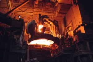
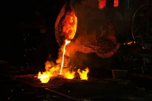
High-Current Transmission
Core Pain Point: The flexible connection cables (الكابلات المبردة بالماء) connecting the power cabinet to the furnace body are the highest failure zones. A break here means immediate production stoppage.
بناء & المخاطر
Water-cooled cables typically consist of stranded copper wires with a central cooling water channel, wrapped in a rubber hose. They act as the “umbilical cord” of the فرن الحث, transmitting thousands or even tens of thousands of Amperes.
Common Failure Modes & وقاية
- Broken Strands & ارتفاع درجة الحرارة (Fatigue):
- Cause: Furnace tilting and electromagnetic vibration cause fatigue fracture of copper strands. Once broken, the effective cross-section decreases, resistance increases, leading to overheating.
- وقاية: Measure DC resistance regularly. If the resistance of a cable increases by 10-15% compared to a new one, replace it immediately.
- Water Blockage:
- Cause: Poor water quality leads to scaling, reducing water flow and causing copper strands to burn out due to poor heat dissipation.
- وقاية: Must use a closed-loop system with pure/distilled water and periodically back-flush the cable water lines.
- Friction & Shorting:
- Cause: Under high current, cables generate immense Lorentz Forces, causing them to swing violently and strike each other, wearing down the insulation.
- وقاية: Use insulating spacers to fix and separate cables, and install abrasion-resistant outer sheaths (such as fireproof canvas).