ในด้านการแปรรูปความร้อนจากอุตสาหกรรมที่ทันสมัย, เตาเหนี่ยวนำมีบทบาทที่ขาดไม่ได้เนื่องจากมีประสิทธิภาพสูง, ความสะอาด, และความแม่นยำ. อย่างไรก็ตาม, เมื่ออุปกรณ์ที่ซับซ้อนนี้ล้มเหลว, งานบำรุงรักษาเป็นมากกว่าแค่งานบำรุงรักษา “ขันสกรูสองสามตัวให้แน่น” ช่างเทคนิคเตาเหนี่ยวนำสมัยใหม่ที่โดดเด่นจะต้องมีความรู้เชิงลึกครอบคลุมทั้งด้านไฟฟ้าและไฮดรอลิก เพื่อวินิจฉัยและแก้ไขปัญหาได้อย่างรวดเร็วและแม่นยำ, สร้างความมั่นใจในความต่อเนื่องในการผลิต.
ส่วนหนึ่ง 1: การวินิจฉัยและการบำรุงรักษาแหล่งจ่ายไฟ IGBT
หัวใจของเตาเหนี่ยวนำคือแหล่งจ่ายไฟความถี่ปานกลาง, และ IGBT (ทรานซิสเตอร์แบบไบโพลาร์เกตแบบหุ้มฉนวน) เป็นแกนหลักของแหล่งจ่ายไฟความถี่กลางสมัยใหม่. ความเสถียรของ IGBT จะกำหนดโดยตรงว่าเตาเหนี่ยวนำสามารถทำงานได้ตามปกติหรือไม่. ดังนั้น, การเรียนรู้การวินิจฉัยแหล่งจ่ายไฟ IGBT เป็นทักษะหลักสำหรับช่างซ่อมบำรุง.
1. ทำความเข้าใจหลักการทำงานของ IGBT และโหมดความล้มเหลวทั่วไป
IGBT เป็นคอมโพสิต, ควบคุมได้อย่างเต็มที่, อุปกรณ์เซมิคอนดักเตอร์กำลังขับเคลื่อนด้วยแรงดันไฟฟ้าที่รวมความต้านทานอินพุตสูงของ MOSFET เข้ากับแรงดันตกคร่อมในสถานะต่ำของ GTR. ในแหล่งจ่ายไฟของเตาเหนี่ยวนำ, IGBT แปลงกำลังไฟฟ้ากระแสตรงที่เรียงกระแสเป็นไฟฟ้ากระแสสลับความถี่ปานกลางที่ความถี่เฉพาะผ่านการสลับความถี่สูง, จึงสร้างสนามแม่เหล็กสลับอันทรงพลังในขดลวดเหนี่ยวนำ.
โหมดความล้มเหลวทั่วไปได้แก่:
- ความเสียหายกระแสเกิน: นี่คือสาเหตุที่พบบ่อยที่สุดของความล้มเหลว. ไม่ว่าจะเป็นกระแสไฟกระชากเมื่อสตาร์ท หรือโหลดลัดวงจร หรือไม่ตรงกันระหว่างการทำงาน, กระแสที่ไหลผ่าน IGBT อาจเกินค่าพิกัดของมัน, การเผาไหม้ชิปในเวลาอันสั้นมาก.
- ความเสียหายจากแรงดันไฟฟ้าเกิน: โครงข่ายไฟฟ้ากระชาก, สายฟ้าฟาด, หรือการเปลี่ยนแปลงโหลดที่รุนแรงสามารถสร้างแรงดันไฟกระชากทั่วขั้วตัวสะสม-ตัวส่งสัญญาณของ IGBT ซึ่งเกินแรงดันไฟฟ้าที่ทนได้, นำไปสู่การล่มสลาย.
- ความเสียหายจากความร้อน: IGBT สร้างการสูญเสียพลังงานในรูปของความร้อนในระหว่างกระบวนการเปลี่ยน. หากระบบทำความเย็นทำงานผิดปกติหรือหากเครื่องทำงานภายใต้สภาวะโอเวอร์โหลดเป็นเวลานาน, อุณหภูมิทางแยกจะเพิ่มขึ้นอย่างต่อเนื่อง, นำไปสู่การสลายความร้อนในที่สุด.
- ความล้มเหลวของไดรเวอร์เกต: วงจรขับมีหน้าที่ในการส่งสัญญาณการสลับที่แม่นยำไปยังเกตของ IGBT. แรงดันไฟฟ้าของไดรเวอร์สูงหรือต่ำเกินไป, หรือสัญญาณการขับเคลื่อนไม่เสถียรหรือมีเสียงดัง, สามารถป้องกันไม่ให้ IGBT เปลี่ยนได้อย่างถูกต้องและอาจทำให้เกิดการยิงทะลุได้ (IGBT ทั้งสองข้างที่ขาดำเนินการพร้อมกัน), ส่งผลให้เกิดไฟฟ้าลัดวงจรและเหนื่อยหน่าย.
2. เทคนิคการวินิจฉัยขั้นสูง
เมื่อต้องเผชิญกับความล้มเหลวของ IGBT, ช่างเทคนิคไม่ควรพอใจกับการเปลี่ยนชิ้นส่วนเพียงอย่างเดียว แต่ควรมีความสามารถในการวิเคราะห์สาเหตุที่แท้จริงของข้อผิดพลาดได้.
- การผสมผสานการทดสอบแบบสถิตกับการวิเคราะห์แบบไดนามิก: การตั้งค่าไดโอดของมัลติมิเตอร์สามารถใช้สำหรับการตรวจสอบคงที่เบื้องต้นของโมดูล IGBT เพื่อตรวจสอบว่ามีการลัดวงจรหรือเปิดระหว่าง C-E และ G-E. อย่างไรก็ตาม, การทดสอบคงที่ตามปกติไม่รับประกันว่าจะปราศจากปัญหาระหว่างการทำงานแบบไดนามิก. ทีมที่มีอุปกรณ์ที่เหมาะสมควรใช้ออสซิลโลสโคป—โดยต้องมั่นใจในความปลอดภัย (โดยใช้โพรบดิฟเฟอเรนเชียลไฟฟ้าแรงสูง)- เพื่อสังเกตรูปคลื่นแรงดันไฟฟ้าเกต-อิมิตเตอร์ของ IGBT (วีจีอี) และรูปคลื่นแรงดันไฟฟ้าของตัวสะสมและตัวปล่อย (วีซีอี).
- วีจีอี รูปคลื่น การวินิจฉัย: รูปคลื่นของไดรฟ์ปกติควรมีความชัน, คลื่นสี่เหลี่ยมที่มั่นคง. หากรูปคลื่นแสดงการแกว่ง, เกินเลย, หรือขอบขึ้น/ลงอย่างช้าๆ, แสดงว่ามีปัญหากับวงจรไดรเวอร์, ต้องมีการตรวจสอบส่วนประกอบต่างๆ เช่น ไดรเวอร์ IC, แหล่งจ่ายไฟ, ออปโตคัปเปลอร์, และตัวต้านทานเกต.
- วีซีอี รูปคลื่น การวินิจฉัย: สังเกตแรงดันไฟฟ้าที่เพิ่มขึ้นในขณะที่ IGBT ปิดเพื่อดูว่าอยู่ภายในพื้นที่การทำงานที่ปลอดภัยหรือไม่. แรงดันไฟฟ้าที่พุ่งสูงเกินไปมักเกี่ยวข้องกับการออกแบบหรือความล้มเหลวของส่วนประกอบวงจร snubber.
- การตีความรหัสข้อผิดพลาดในเชิงลึก: โดยทั่วไปแล้วแหล่งจ่ายไฟของเตาเหนี่ยวนำสมัยใหม่จะมีฟังก์ชันการป้องกันที่ครอบคลุมและแสดงรหัสที่เกี่ยวข้องเมื่อเกิดข้อผิดพลาด. ช่างเทคนิคต้องทำมากกว่าการค้นหาความหมายเพียงผิวเผินของโค้ด (เช่น, “กระแสเกิน”) ในคู่มือ. พวกเขาควรวิเคราะห์บริบทที่เกิดข้อผิดพลาด ไม่ว่าจะเป็นในระหว่างการเริ่มต้นระบบก็ตาม, เพิ่มพลัง, หรือการดำเนินการด้านพลังงานที่มีเสถียรภาพ—เพื่อจำกัดขอบเขตการสอบสวนให้แคบลง.
ส่วนหนึ่ง 2: ทำความเข้าใจและประยุกต์ใช้ PLC ในการควบคุมเตาเผา
ถ้า IGBT คือหัวใจ, แล้วบมจ (คอนโทรลเลอร์ลอจิกที่ตั้งโปรแกรมได้) คือสมองของเตาเหนี่ยวนำ. รับผิดชอบการทำงานอัตโนมัติของระบบทั้งหมด, การตรวจสอบสถานะ, การแจ้งเตือนข้อผิดพลาด, และการประสานความปลอดภัย. การทำความเข้าใจลอจิก PLC เป็นสิ่งสำคัญสำหรับการวินิจฉัย “ความผิดพลาดที่อ่อนนุ่ม” ที่ไม่ได้เกิดจากความเสียหายโดยตรงของฮาร์ดแวร์.
1. การเรียนรู้ขั้นตอนการทำงานของ PLC ขั้นพื้นฐานอย่างเชี่ยวชาญ
PLC ทำงานในกระบวนการสแกนแบบวนรอบ: ป้อนข้อมูล สแกน -> การทำงานของโปรแกรม -> เอาท์พุท อัปเดต. ซึ่งหมายความว่า PLC จะอ่านสัญญาณอินพุตทั้งหมด (เช่น, ปุ่ม, สถานะเซ็นเซอร์), คำนวณตามลอจิกโปรแกรมที่ตั้งไว้ล่วงหน้า, และสุดท้ายจะอัพเดตสัญญาณเอาท์พุตทั้งหมด (เช่น, คอนแทคเตอร์การขับขี่, โซลินอยด์วาล์ว, ไฟแสดงสถานะ).
2. เข้าใจตรรกะการควบคุมหลัก
ในขณะที่ช่างเทคนิคอาจไม่จำเป็นต้องเขียนโปรแกรม PLC ที่ซับซ้อนตั้งแต่เริ่มต้น, พวกเขาจะต้องสามารถอ่านและทำความเข้าใจไดอะแกรมแลดเดอร์หรือไดอะแกรมบล็อกฟังก์ชันที่เกี่ยวข้องกับฟังก์ชันหลักของเตาเหนี่ยวนำ.
- เริ่มและหยุดลอจิก: ทำความเข้าใจเงื่อนไขที่จำเป็นสำหรับคอนแทคเตอร์วงจรหลักในการเชื่อมต่อ, ซึ่งประกอบด้วยชุดระบบล็อคเพื่อความปลอดภัย เช่น ปุ่มหยุดฉุกเฉิน, รีเลย์แรงดันน้ำ, และรีเลย์อุณหภูมิ, ซึ่งทั้งหมดจะต้องได้รับความพึงพอใจ.
- ลอจิกการควบคุมพลังงาน: รู้ว่า PLC ควบคุมการตั้งค่าพลังงานของแหล่งจ่ายไฟ IGBT ผ่านเอาต์พุตแบบอะนาล็อกอย่างไร (เช่น, 0-10สัญญาณ V หรือ 4-20mA). นี่เป็นสิ่งสำคัญสำหรับการวินิจฉัยปัญหาเช่น “พลังจะไม่เพิ่มขึ้น” หรือ “อำนาจไม่สามารถควบคุมได้”
- ลอจิกสัญญาณเตือนและลูกโซ่: นี่คือกุญแจสำคัญในการแก้ไขปัญหา. เมื่อ PLC ตรวจพบสัญญาณผิดปกติ (เช่น, การไหลของน้ำหล่อเย็นต่ำกว่าค่าที่ตั้งไว้, อุณหภูมิร่างกายของเตาสูงเกินไป), โดยจะดำเนินการลอจิกสัญญาณเตือนที่เกี่ยวข้อง และอาจทริกเกอร์อินเทอร์ล็อคเพื่อบังคับให้ลดกำลังหรือปิดระบบ.
3. การใช้ PLC เพื่อการวินิจฉัยข้อผิดพลาดอย่างมีประสิทธิภาพ
- การตรวจสอบออนไลน์: เชื่อมต่อกับ PLC ด้วยซอฟต์แวร์การเขียนโปรแกรมเพื่อตรวจสอบสถานะของจุด I/O และตัวแปรข้อมูลภายในแบบเรียลไทม์. ตัวอย่างเช่น, เมื่อ “แรงดันน้ำต่ำ” สัญญาณเตือนเกิดขึ้น, คุณสามารถดูได้โดยตรงในซอฟต์แวร์ซึ่งสวิตช์ความดัน (จุดเข้า) สัญญาณไม่ได้เปิดใช้งาน, ช่วยให้สามารถระบุตำแหน่งเซ็นเซอร์หรือสายไฟที่ชำรุดได้อย่างรวดเร็ว.
- การตีความข้อมูลสัญญาณเตือน: เอชเอ็มไอ (ส่วนต่อประสานระหว่างมนุษย์กับเครื่องจักร) ของเตาเหนี่ยวนำสมัยใหม่มักจะให้ประวัติการแจ้งเตือนโดยละเอียด. ช่างเทคนิคจำเป็นต้องวิเคราะห์ประเภทของสัญญาณเตือนอย่างรอบคอบ, เวลาที่มันเกิดขึ้น, และไม่ว่าจะมีสัญญาณเตือนภัยอื่นๆ ร่วมด้วยหรือไม่. ซึ่งมักจะให้เบาะแสในการแก้ปัญหา. ตัวอย่างเช่น, หนึ่ง “อินเวอร์เตอร์ผิดพลาด” สัญญาณเตือนที่เกิดขึ้นทันทีหลังจาก “อุณหภูมิน้ำหล่อเย็นสูง” สัญญาณเตือนแสดงให้เห็นอย่างชัดเจนว่าสาเหตุที่แท้จริงอยู่ที่ระบบทำความเย็น.
ส่วนหนึ่ง 3: การออกแบบและบำรุงรักษาวงจรน้ำหล่อเย็น
สำหรับเตาเหนี่ยวนำที่สามารถกินพลังงานได้หลายร้อยกิโลวัตต์หรือแม้แต่เมกะวัตต์, ระบบระบายความร้อนที่มีประสิทธิภาพและเชื่อถือได้คือเส้นชีวิตของมัน. ความประมาทเลินเล่อในส่วนใดส่วนหนึ่งของกระบวนการทำความเย็นสามารถนำไปสู่ความล้มเหลวอย่างร้ายแรงของแหล่งจ่ายไฟ IGBT หรือขดลวดเหนี่ยวนำ.
1. ทำความเข้าใจหลักการออกแบบวงจรทำความเย็น
ระบบทำความเย็นของเตาเหนี่ยวนำโดยทั่วไปจะแบ่งออกเป็นสองส่วนหลัก:
- การระบายความร้อนของพาวเวอร์ซัพพลาย: วงจรนี้จะทำความเย็นส่วนประกอบอิเล็กทรอนิกส์กำลังสูงเป็นหลัก เช่น โมดูล IGBT, สะพานเรียงกระแส, และตัวเก็บประจุแบบเรโซแนนซ์. ส่วนนี้มีข้อกำหนดด้านคุณภาพน้ำที่สูงมาก และมักจะใช้ ระบบหมุนเวียนน้ำปราศจากไอออนแบบวงปิด เพื่อป้องกันตะกรันสะสมและไฟฟ้ารั่วเนื่องจากมีค่าการนำไฟฟ้าสูง.
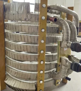
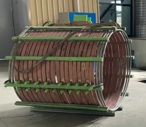
- ตัวเตา (ม้วน) ระบายความร้อน: วงจรนี้จะทำความเย็นขดลวดเหนี่ยวนำและชิ้นส่วนโครงสร้างของเตาเป็นหลัก. เนื่องจากภาระความร้อนอันมหาศาล, ส่วนนี้มักจะใช้ไฟล์ เปิด- หรือระบบหมุนเวียนแบบวงปิด ด้วยอัตราการไหลที่มากขึ้น.
พารามิเตอร์การออกแบบที่สำคัญ:
- อัตราการไหล: ต้องรับประกันการไหลที่เพียงพอเพื่อนำความร้อนที่เกิดขึ้นออกไป. การทำความเย็นแต่ละสาขาควรมีตัวตรวจสอบการไหลที่เชื่อมต่อกับ PLC.
- ความดัน: จำเป็นต้องมีแรงดันน้ำที่เพียงพอเพื่อเอาชนะความต้านทานของท่อ และให้แน่ใจว่าน้ำไปถึงจุดทำความเย็นที่จำเป็นทั้งหมด.
- อุณหภูมิ: อุณหภูมิของน้ำขาเข้าไม่ควรสูงเกินไป, เนื่องจากจะทำให้ประสิทธิภาพการทำความเย็นลดลง. ในเวลาเดียวกัน, ควรหลีกเลี่ยงอุณหภูมิที่ต่ำเกินไปเพื่อป้องกันการควบแน่นในช่วงฤดูร้อน, ซึ่งอาจทำให้เกิดปัญหาฉนวนไฟฟ้าได้.
- คุณภาพน้ำ: ค่าการนำไฟฟ้า, ค่า pH, และความกระด้างของน้ำได้รับการควบคุมอย่างเข้มงวด, โดยเฉพาะวงจรระบายความร้อนของแหล่งจ่ายไฟ. น้ำที่มีความนำไฟฟ้าสูงจะเพิ่มความเสี่ยงต่อการรั่วไหลของกระแสไฟฟ้า, ในขณะที่น้ำกระด้างก่อให้เกิดตะกรันได้ง่ายซึ่งสามารถปิดกั้นช่องระบายความร้อนที่ละเอียดอ่อนได้.
2. การวินิจฉัยและบำรุงรักษาความผิดปกติของระบบทำความเย็น
- ข้อผิดพลาดทั่วไป:
- การไหลไม่เพียงพอ: อาจเกิดจากปั๊มชำรุด, ตัวกรองอุดตัน, ท่อปรับขนาด, หรือการรั่วไหล.
- อุณหภูมิของน้ำสูง: อาจเกิดจากประสิทธิภาพของหอทำความเย็น/เครื่องทำความเย็นลดลง, ครีบระบายความร้อนสกปรก, พัดลมทำงานผิดปกติ, หรืออุณหภูมิแวดล้อมสูง.
- แรงดันน้ำผิดปกติ: อาจเกิดจากการรั่วซึม, ปัญหาปั๊ม, หรืออากาศที่ติดอยู่ในระบบ.
- วิธีการวินิจฉัย:
- การตรวจสอบอย่างเป็นระบบ: ติดตาม “จากต้นทางถึงปลายทาง” หลักการ, ตรวจสอบถังเก็บน้ำ, ปั๊ม, กรอง, เครื่องแลกเปลี่ยนความร้อน, และวาล์วและมิเตอร์วัดการไหลของแต่ละสาขาตามลำดับ.
- ตรวจสอบความแตกต่างของความดันและอุณหภูมิ: การวัดแรงดันตกคร่อมและความแตกต่างของอุณหภูมิทั้งทางเข้าและทางออกของตัวกรองและเครื่องแลกเปลี่ยนความร้อนเป็นวิธีที่มีประสิทธิภาพในการพิจารณาว่าสิ่งเหล่านั้นอุดตันหรือมีประสิทธิภาพลดลงหรือไม่.
- การทดสอบคุณภาพน้ำเป็นประจำ: การทดสอบค่าการนำไฟฟ้าและ pH ของน้ำหล่อเย็นเป็นระยะๆ และการเปลี่ยนเรซินแลกเปลี่ยนไอออนหรือสารหล่อเย็นแบบเติมตามความจำเป็นเป็นหัวใจสำคัญของการบำรุงรักษาเชิงป้องกัน.
บทสรุป: การเปลี่ยนแปลงจากผู้ดำเนินการไปสู่นักแก้ปัญหา
การบำรุงรักษาเตาเหนี่ยวนำสมัยใหม่มีการพัฒนามายาวนานเกินกว่าขอบเขตของช่างกลและช่างไฟฟ้าแบบดั้งเดิม. ช่างเทคนิคต้องมีความสามารถรอบด้านซึ่งสามารถบูรณาการความรู้เกี่ยวกับระบบอัตโนมัติทางไฟฟ้าและพลศาสตร์ของไหลได้. เมื่อสมาชิกในทีมบำรุงรักษาทุกคนสามารถทำได้:
- ตีความ รูปคลื่นของไดรฟ์ของ IGBT, ไม่ใช่แค่เปลี่ยนโมดูลเท่านั้น;
- เข้าใจ ลอจิกประสานใน PLC, ไม่ใช่แค่รีเซ็ตการปลุก;
- วิเคราะห์ อัตราการไหลและความแตกต่างของอุณหภูมิของระบบทำความเย็น, ไม่ใช่แค่ทำความสะอาดหน้าจอตัวกรอง;
แล้ว, ความสามารถของทีมในการแก้ปัญหาที่ซับซ้อนจะบรรลุผลอย่างก้าวกระโดดในเชิงคุณภาพ. การเปลี่ยนแปลงนี้จากแบบพาสซีฟ “ขันสกรู” ดำเนินการเชิงรุก “นักแก้ปัญหา” เป็นความต้องการใหม่ที่อุตสาหกรรมสมัยใหม่มีให้กับช่างซ่อมบำรุงและยังเป็นกุญแจสำคัญในการเพิ่มคุณค่าทางวิชาชีพของตนเองอีกด้วย.