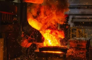
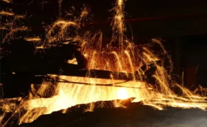
ইন্ডাকশন ফার্নেস কুখ্যাত “সমস্যা সৃষ্টিকারী” শিল্প শক্তি গ্রিড মধ্যে. সাধারণ হিসাবে নন-লিনিয়ার লোড, গ্রিডের সাথে গলানোর দক্ষতার ভারসাম্য বজায় রাখা “স্বাস্থ্য” বৈদ্যুতিক প্রকৌশলী এবং সুবিধা পরিচালকদের জন্য একটি ধ্রুবক যুদ্ধ.
সরঞ্জাম হস্তক্ষেপ & অদৃশ্য ক্ষতি
কোর পেইন পয়েন্ট: ট্রান্সফরমার সম্পূর্ণ লোড না হওয়া সত্ত্বেও কেন অতিরিক্ত গরম হয়? সংলগ্ন ওয়ার্কশপে সিএনসি মেশিনগুলো আপাত কারণ ছাড়াই অ্যালার্ম করছে কেন??
হারমোনিক জেনারেশনের প্রক্রিয়া
একটি আনয়ন চুল্লি পাওয়ার সাপ্লাই এর মূল মধ্যে রয়েছে সংশোধন (এসি থেকে ডিসি) এবং বিপরীত (ডিসি থেকে এসি) পর্যায়. যখন উচ্চ ক্ষমতা সম্পন্ন Thyristors (এসসিআর) বা আইজিবিটি উচ্চ-ফ্রিকোয়েন্সি স্যুইচিং সঞ্চালন করে, বর্তমান তরঙ্গরূপ বিকৃত হয়. এটি একটি স্ট্যান্ডার্ড সাইন ওয়েভ থেকে বিরত থাকে, উচ্চ-ক্রম হারমোনিক্স তৈরি করা (প্রাথমিকভাবে 5 ম, 7ম, 11ম, এবং 13 তম আদেশ).
ক্ষতির কারণ
- ট্রান্সফরমার ওভারহিটিং: উচ্চ-ফ্রিকোয়েন্সি সুরেলা স্রোত গুরুতর সৃষ্টি করে ত্বকের প্রভাব কন্ডাক্টরের মধ্যে, ক্রমবর্ধমান ঘুর প্রতিরোধের ক্ষতি; তারা লোহার কোরে হিস্টেরেসিস এবং এডি কারেন্টের ক্ষতিও বাড়ায়.
- ক্যাপাসিটরের বিস্ফোরণ: যদি কারখানার ক্ষতিপূরণ ক্যাপাসিটর ব্যাংক গঠন করে a সমান্তরাল অনুরণন একটি নির্দিষ্ট সুরেলা ফ্রিকোয়েন্সিতে সিস্টেম আবেশ সঙ্গে, ভোল্টেজ এবং কারেন্ট বেশ কয়েকবার বাড়িয়ে দিতে পারে, ক্যাপাসিটর ভাঙ্গন বা বিস্ফোরণের দিকে পরিচালিত করে.
- নির্ভুলতা যন্ত্রের ব্যর্থতা: হারমোনিক ভোল্টেজ নিয়ন্ত্রণ সার্কিটে শূন্য-ক্রসিং সনাক্তকরণে হস্তক্ষেপ করে, CNC কন্ট্রোলার ঘটাচ্ছে, পিএলসিএস, অথবা ত্রুটিপূর্ণ রিলে.
সমাধান: ফিল্টার নির্বাচন
| সমাধান | নীতি | পেশাদার | কনস | প্রযোজ্য দৃশ্যকল্প |
| প্যাসিভ ফিল্টার | Inductors ব্যবহার করে (এল) & ক্যাপাসিটার (গ) নির্দিষ্ট ফ্রিকোয়েন্সিগুলির জন্য একটি কম-প্রতিবন্ধক পথ তৈরি করতে সিরিজে (যেমন, 5ম, 7ম). | কম খরচে, পরিপক্ক প্রযুক্তি, সহজ গঠন. | শুধুমাত্র নির্দিষ্ট ফ্রিকোয়েন্সি ফিল্টার করতে পারেন; গ্রিড প্রতিবন্ধকতা সংবেদনশীল; অনুরণন ঝুঁকি বিদ্যমান. | স্থিতিশীল লোড এবং সীমিত বাজেট সহ ঐতিহ্যবাহী কারখানা. |
| সক্রিয় পাওয়ার ফিল্টার (এপিএফ) | লোড কারেন্টে হারমোনিক উপাদান সনাক্ত করে এবং সমান প্রশস্ততার কিন্তু বিপরীত পর্যায়ের একটি ক্ষতিপূরণ কারেন্ট ইনজেকশন করে. | গতিশীলভাবে বিভিন্ন ফ্রিকোয়েন্সি ফিল্টার করে; কোন অনুরণন ঝুঁকি; দ্রুত প্রতিক্রিয়া (মাইক্রোসেকেন্ড). | বেশি খরচ, অপেক্ষাকৃত উচ্চ শক্তি খরচ. | আধুনিক কারখানা উচ্চ বিদ্যুতের মানের প্রয়োজন (সংবেদনশীল CNC সরঞ্জাম ধারণকারী). |
প্রতিক্রিয়াশীল শক্তি ক্ষতিপূরণ
কোর পেইন পয়েন্ট: দ্য “পাওয়ার ফ্যাক্টর সারচার্জ” (শাস্তি) মাসিক বিদ্যুতের বিল বেশি থাকে, এবং ট্রান্সফরমারের ক্ষমতা অপর্যাপ্ত বলে মনে হচ্ছে.
লো পাওয়ার ফ্যাক্টরের মূল
ইন্ডাকশন ফার্নেস গরম করার জন্য ইলেক্ট্রোম্যাগনেটিক ইন্ডাকশন ব্যবহার করে, লোড মূলত একটি বৃহদায়তন মানে ইন্ডাকটিভ কয়েল. ইন্ডাকটিভ লোডের কারণে কারেন্ট ভোল্টেজ থেকে পিছিয়ে যায়, উল্লেখযোগ্য উৎপন্ন প্রতিক্রিয়াশীল শক্তি (প্র).
পাওয়ার ফ্যাক্টর (পিএফ) = cosΦ = P (সক্রিয়) / এস(আপাত)
যদি cosΦ খুব কম হয় (যেমন, 0.6), এর মানে হল ট্রান্সফরমারটি প্রচুর পরিমাণে অ্যাপারেন্ট পাওয়ার এস আউটপুট করছে, কিন্তু খুব কম দরকারী কাজ সম্পাদন করা পি.
ক্ষতিপূরণ কৌশল: ক্যাপাসিটর ব্যাংক
বাসবারের সাথে সংযুক্ত ক্যাপাসিটর ব্যাঙ্কগুলি ফার্নেস থেকে ল্যাগিং ইনডাকটিভ কারেন্ট অফসেট করতে অগ্রণী ক্যাপাসিটিভ কারেন্ট সরবরাহ করে.
- শাস্তি এড়িয়ে চলুন: পাওয়ার ফ্যাক্টর উপরে উত্থাপন 0.95 সরাসরি ইউটিলিটি জরিমানা দূর করে এবং এমনকি প্রণোদনার জন্য যোগ্যতা অর্জন করতে পারে.
- ট্রান্সফরমার রিলিজ করুন ক্ষমতা:
- মামলা: PF=0.6 সহ একটি 2000kVA ট্রান্সফরমার শুধুমাত্র একটি 1200kW লোড সমর্থন করতে পারে.
- উন্নত: PF=0.95 সহ, একই ট্রান্সফরমার একটি 1900kW লোড সমর্থন করতে পারে.
- উপসংহার: ক্ষতিপূরণকারী প্রতিক্রিয়াশীল শক্তি কার্যকরভাবে যোগ করে “বিনামূল্যে” ব্যয়বহুল আপগ্রেডের প্রয়োজন ছাড়াই ট্রান্সফরমারের ক্ষমতা.
দ্রষ্টব্য: গুরুতর সুরেলা সহ সিস্টেমে, ক্যাপাসিটর ব্যাঙ্ক সিরিজ চুল্লি সহ (detuned চুল্লি) ব্যবহার করা আবশ্যক. অন্যথায়, সুরেলা স্রোত ক্যাপাসিটারে উঠবে, ক্ষতি ঘটাচ্ছে.
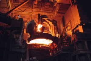
উচ্চ-কারেন্ট ট্রান্সমিশন
কোর পেইন পয়েন্ট: নমনীয় সংযোগ তারের (জল ঠান্ডা তারের) ফার্নেস বডির সাথে পাওয়ার ক্যাবিনেটের সংযোগ সবচেয়ে বেশি ব্যর্থতা জোন. এখানে একটি বিরতি মানে অবিলম্বে উত্পাদন বন্ধ.
গঠন & বিপত্তি
জল-শীতল তারগুলি সাধারণত একটি কেন্দ্রীয় শীতল জলের চ্যানেল সহ আটকে থাকা তামার তারগুলি নিয়ে গঠিত, একটি রাবার পায়ের পাতার মোজাবিশেষ মধ্যে আবৃত. তারা হিসাবে কাজ “আম্বিলিক্যাল কর্ড” এর আনয়ন চুল্লি, হাজার হাজার বা এমনকি হাজার হাজার অ্যাম্পিয়ার প্রেরণ করে.
সাধারণ ব্যর্থতার মোড & প্রতিরোধ
- ভাঙ্গা Strands & অতিরিক্ত উত্তাপ (ক্লান্তি):
- কারণ: ফার্নেস টিল্টিং এবং ইলেক্ট্রোম্যাগনেটিক কম্পন তামার স্ট্র্যান্ডের ক্লান্তি ফাটল সৃষ্টি করে. একবার ভেঙে যায়, কার্যকর ক্রস-সেকশন হ্রাস পায়, প্রতিরোধ ক্ষমতা বৃদ্ধি পায়, অতিরিক্ত উত্তাপের দিকে পরিচালিত করে.
- প্রতিরোধ: নিয়মিত ডিসি প্রতিরোধের পরিমাপ করুন. যদি একটি তারের প্রতিরোধ ক্ষমতা বৃদ্ধি পায় 10-15% একটি নতুন একটি তুলনায়, অবিলম্বে এটি প্রতিস্থাপন করুন.
- পানি অবরোধ:
- কারণ: দরিদ্র জল মানের স্কেলিং বাড়ে, জলের প্রবাহ হ্রাস করা এবং তামার স্ট্র্যান্ডগুলি দুর্বল তাপ অপচয়ের কারণে পুড়ে যায়.
- প্রতিরোধ: বিশুদ্ধ/পাতিত জল সহ একটি ক্লোজড-লুপ সিস্টেম ব্যবহার করতে হবে এবং পর্যায়ক্রমে তারের জলের লাইনগুলিকে ব্যাক-ফ্লাশ করতে হবে.
- ঘর্ষণ & শর্টিং:
- কারণ: উচ্চ স্রোতের অধীনে, তারের প্রচুর উৎপন্ন হয় লরেন্টজ ফোর্সেস, যার ফলে তারা হিংস্রভাবে দুলছে এবং একে অপরকে আঘাত করছে, নিরোধক নিচে পরা.
- প্রতিরোধ: তারগুলি ঠিক করতে এবং আলাদা করতে অন্তরক স্পেসার ব্যবহার করুন, এবং ঘর্ষণ-প্রতিরোধী বাইরের আবরণ ইনস্টল করুন (যেমন ফায়ারপ্রুফ ক্যানভাস).