Topic 1: The Meniscus Effect
How it impacts slag removal and lining life.
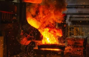
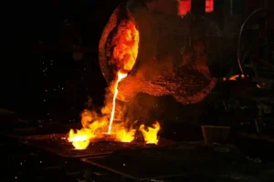
When an induction furnace operates at full power, you will observe that the molten metal surface is not flat; instead, it rises in the center to form a dome shape. This is known as the “Meniscus.”
The Physical Principle:
This is the result of the interaction between Electromagnetic Pressure and Hydrostatic Pressure. The magnetic field generated by the induction coil induces a current within the molten metal. According to the Lorentz Force Law, the interaction between the magnetic field and the induced current creates an inward electromagnetic force (F = J * B). This force attempts to “squeeze” the metal. Due to the incompressibility of the liquid, the metal is forced to move upward toward the center where the pressure is lower, creating the bulge.
Relationship between Meniscus Height, Power, and Frequency:
- Power (P): The higher the power, the greater the current, resulting in stronger electromagnetic squeezing force and a higher meniscus.
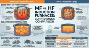
- Frequency (f): There is an inverse relationship. Lower frequency results in deeper electromagnetic wave penetration and more vigorous stirring, leading to a higher meniscus. Conversely, high-frequency furnaces typically exhibit a flatter meniscus.
Practical Impact Analysis:
- Positive Effect (Assisting Slag Removal): The rising meniscus pushes non-metallic inclusions and slag floating on the surface toward the furnace walls (a relatively cooler zone). This makes deslaging easier, as the slag naturally aggregates at the edges.
- Negative Effect (Accelerated Erosion):
- Slag Line Erosion: As slag is pushed against the lining walls, ang “slag line” area is subjected to a dual attack: chemical corrosion from the slag and mechanical scouring from the metal. A higher meniscus causes more surface fluctuation, exacerbating physical wear in this zone.
- Lid Risks: Extreme low-frequency, high-power operation can cause the meniscus to rise too high, potentially touching the furnace lid or causing spillage.
Topic 2: The Skin Effect
Deep Dive: How frequency selection determines melting efficiency.
Why do melting fine chips and melting large steel blocks require different frequencies? The answer lies in “how deep the current can drill.”
The Concept & Formula:
When alternating current (AC) passes through a conductor, the current distribution is non-uniform; the majority of the current tends to flow on the surface (ang “skin”) of the conductor. Current density decays exponentially from the surface toward the center.
We define the Penetration Depth (or Reference Depth, δ) as the depth at which the current density drops to 1/e (approximately 37%) of the surface current density.
Key Conclusion: Frequency (f) is inversely proportional to Penetration Depth (δ).
Scenario Analysis:
- Melting Fine Charge (hal., Drill Chips, Turnings): Requires High Frequency
- Reason: The diameter of the scrap is small. If low frequency (deep penetration) is used, the current might “pass through” the entire piece, causing the effects of the positive and negative half-cycles to cancel each other out, or the penetration depth may exceed the radius of the scrap, failing to induce effective eddy currents for heating.
- Strategy: High-frequency current has a very shallow “skin depth,” allowing it to effectively “grip” the surface of the fine material to generate heat.
- Melting Large Steel Scrap: Requires Lower Frequency
- Reason: If extremely high frequency is used on large blocks, the current flows only in a very thin surface layer. While the surface melts, the core remains cold. This leads to “surface overheating” with a “frozen center,” significantly prolonging melting time.
- Strategy: Lower frequency allows current to penetrate deeper into the metal, achieving uniform, rapid heating from the inside out.
Topic 3: Fluid Dynamics in Induction Furnaces
Balancing Stirring Dead Zones and Excessive Scouring.
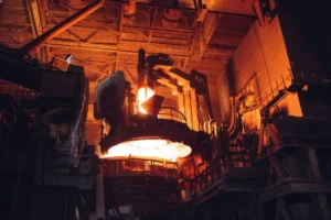
The molten metal inside an induction furnace is never static; it is in a state of vigorous motion. Understanding this flow pattern is critical for controlling alloy composition and protecting the furnace lining.
Flow Pattern:
A typical induction furnace flow field presents a Double Toroidal Loop.
- Upper Loop: Metal rises along the central axis (forming the meniscus), spreads outward, and flows down along the furnace walls.
- Lower Loop: Metal flows down along the central axis, spreads outward at the bottom, and flows up along the furnace walls.
- The two loops meet in the middle of the induction coil and flow inward toward the center.
The Art of Balance:
- Stirring Dead Zones:
- Lokasyon: Typically found in the bottom corners (where the lower loop doesn’t reach) or the very top near the walls.
- Consequence: If stirring force is insufficient (frequency too high or power too low), heavy alloying elements (like Tungsten or Molybdenum) may settle in these dead zones. This leads to inhomogeneity in the entire heat. A sample might pass analysis, but the cast product is scrapped due to segregation.
- Excessive Scouring:
- Lokasyon: Usually occurs in the mid-lower section of the coil (where the two loops converge) and at the slag line.
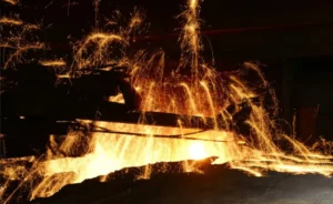
- Consequence: If frequency is lowered too much to increase stirring, the high-velocity molten metal scours the lining like a sandblaster. This mechanical erosion rapidly strips away the protective layer of the lining, drastically shortening campaign life and potentially leading to a run-out.
Summary
Mastering these physical principles helps you advance from an “Operator” to a “Process Expert”:
- The Meniscus indicates whether your power density is too high.
- The Skin Effect guides you to select the correct frequency range based on scrap size.
- Fluid Dynamics helps you find the optimal balance point between “compositional homogeneity” at “lining life.”