Induction heating, as a highly efficient, clean, and controllable heating method, plays a vital role in industrial production. The design and optimization of its core component—the induction coil—directly determine the success or failure of the entire heating system. This article provides an in-depth exploration of how different induction coil shapes and materials affect heating efficiency and uniformity, and discusses the application of Computer-Aided Design (CAD) and simulation tools to provide optimal solutions for specific application needs.
Fundamental Principles of Induction Heating and the Core Role of the Coil
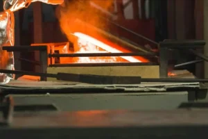
Induction heating is based on Faraday’s Law of Electromagnetic Induction. When an alternating current flows through an induction coil, it generates a changing magnetic field around it. When a conductive workpiece is placed within this field, eddy currents are induced inside the workpiece. As these eddy currents flow through the material’s resistance, they generate Joule heat (P=I2R), causing the workpiece to heat up. For magnetic materials, hysteresis losses also contribute a portion of the heat.
The core role of the induction coil in this process is to efficiently convert electrical energy from the power supply into an alternating magnetic field of a specific shape and intensity, and to precisely couple this field to the target heating area of the workpiece. Therefore, the coil’s design is the “conductor’s baton” that dictates energy conversion efficiency, heating patterns, and temperature distribution.
The Art of Coil Shape
The geometry of the coil is one of the most critical factors affecting the heating outcome. Different shapes determine the distribution of magnetic flux lines, which in turn dictates the path and density of the eddy currents in the workpiece, ultimately creating a specific heating pattern.
| Coil Shape | Diagram | Description & Application |
| Helical/Solenoid Coil | Commonly used for heating cylindrical or rod-shaped workpieces, such as the full-body heating or heat treatment of shafts, pipes, and bars. | Efficiency: High coupling efficiency as magnetic flux lines pass effectively through the workpiece. The smaller the gap (coupling distance) between the coil and the workpiece, the higher the efficiency. Uniformity: By adjusting the pitch between coil turns, end effects can be compensated for to achieve uniform axial heating. More turns result in a longer heating zone. |
| Pancake/Flat Coil | Primarily used for heating flat surfaces or the ends of workpieces. The magnetic field is concentrated directly beneath the coil. | Efficiency: Suitable for surface heating, but the magnetic field tends to diverge, causing some energy loss to the surrounding space. Uniformity: The magnetic field is weaker at the center and stronger at the edges. Uniformity can be improved by adjusting the density of the coil windings. |
| Hairpin/U-shaped Coil | Suitable for scan heating of long, narrow areas or for localized heating of specific edges. | Efficiency: Energy is concentrated within the U-shape and at its tip, resulting in high local heating efficiency. Uniformity: Primarily used for non-uniform heating, but can achieve a uniform treatment over a strip-like area when moved. |
| Internal/ID Coil | Used for heating the internal bores or surfaces of workpieces, such as bearing rings or the inner walls of pipes. | Efficiency: Design is challenging because the magnetic field outside the coil is not utilized. Often requires the use of flux concentrators to confine the magnetic field within the bore to improve efficiency. Uniformity: Centering of the coil is critical; eccentricity can lead to severe non-uniform heating. |
| Profiled/Custom Coil | Custom-made to fit the complex geometry of a workpiece (e.g., gears, crankshafts) to achieve precise contour heating. | Efficiency & Uniformity: The ultimate design goal. By precisely controlling the distance and angle between each part of the coil and the workpiece, highly efficient and uniform heating can be achieved on complex surfaces to meet specific performance requirements. |
The Science of Material Selection
The induction coil itself generates heat due to the current flowing through it. Therefore, material selection is crucial as it directly affects the coil’s electrical efficiency and service life.
- High-Purity Oxygen-Free Copper: This is the most common material for induction coils. Its excellent electrical conductivity (low resistance) minimizes the coil’s own I²R losses, thereby increasing overall electrical efficiency. It is typically formed into hollow tubing to allow for water cooling, which is essential for high-power, long-duration applications.
- Litz Wire: Litz wire consists of multiple fine strands of individually insulated copper wire woven together. In high-frequency applications (typically > 50 kHz), the “skin effect” and “proximity effect” cause current to concentrate on the conductor’s surface and on the adjacent sides of neighboring conductors. This increases effective AC resistance and reduces efficiency. The design of Litz wire forces the current to be distributed evenly throughout the entire conductor cross-section, significantly reducing AC resistance at high frequencies and dramatically improving coil efficiency.
- Flux Concentrators: While not a coil material themselves, flux concentrators (such as ferrites or laminated silicon steel) are used in conjunction with coils to optimize the heating process. They are placed around the coil to “guide” and “focus” the magnetic flux lines, coupling them more effectively into specific areas of the workpiece. This not only significantly increases heating efficiency (energy savings can reach 30-50%) but also improves heating uniformity and reduces unintentional heating of surrounding metal components.
The Revolutionary Role of Computer-Aided Design (CAD) and Simulation
Traditional induction coil design relied heavily on experience and iterative physical experiments, which was costly and time-consuming. The advent of modern CAD and CAE (Computer-Aided Engineering) simulation tools has completely transformed this landscape.
- Computer-Aided Design (CAD): Using software like AutoCAD® or SolidWorks®, engineers can create precise 2D or 3D digital models of the workpiece, coil, flux concentrators, and quenching fixtures. This provides the accurate geometric input required for subsequent simulation analysis and is the first step toward creating a “digital twin.”
- Electromagnetic-Thermal Coupled Simulation: Using specialized Finite Element Analysis (FEA) software (such as ANSYS®, COMSOL Multiphysics®, or CENOS™), engineers can simulate the entire induction heating process on a computer:
- Electromagnetic Field Analysis: The software can accurately calculate the magnetic field distribution generated by the coil at a given current and frequency, as well as the path and density of the eddy currents within the workpiece. This allows designers to visualize where heat will be generated, enabling them to optimize the coil’s shape, number of turns, and position relative to the workpiece.
- Thermal Analysis: The heat source distribution calculated from the electromagnetic analysis is used as input for a transient thermal analysis. This can predict the temperature change over time at any point in the workpiece, evaluate heating uniformity and ramp-up rates, and forecast the final hardened layer depth and microstructure.
- Optimization and Iteration: Engineers can rapidly test different design scenarios in a virtual environment (e.g., changing coil diameter, adjusting flux concentrator shape, varying frequency and power) and compare their heating effects. This allows them to find the optimal design before manufacturing any physical prototypes, drastically shortening the development cycle, reducing costs, and achieving a level of optimization difficult to reach through traditional trial-and-error methods.
Addressing Specific Application Needs through a Holistic Approach
The optimal induction coil design is always a balance between efficiency, uniformity, cost, and the specific needs of the application.
- Surface Hardening: Requires rapidly heating the surface layer of a workpiece while keeping the core at a lower temperature. This typically involves using a higher frequency to leverage the skin effect and designing a closely coupled, profiled coil.
- Through Heating / Forging: Requires heating the entire workpiece uniformly to a high temperature. This usually calls for a lower frequency to achieve deeper current penetration and a helical coil with a looser pitch, sometimes combined with workpiece rotation.
- Welding / Brazing: Requires concentrating heat precisely in the joint area. Specially designed hairpin or annular coils are often used, frequently in combination with flux concentrators to focus the energy.
Conclusion
The design and optimization of induction coils is a comprehensive discipline that integrates electromagnetics, thermodynamics, material science, and engineering practice. By scientifically selecting the coil’s shape (to define the heating pattern) and material (to determine electrical efficiency and lifespan), and by leveraging the powerful tools of modern CAD modeling and simulation analysis, it is possible to achieve unprecedented precision in predicting and controlling the heating process. This simulation-driven design approach not only meets the demands of various complex and stringent applications but also significantly enhances heating efficiency and product quality, serving as the core driving force for the continuous advancement of induction heating technology.