A hardcore comparison and energy efficiency analysis of series vs. parallel resonant circuits
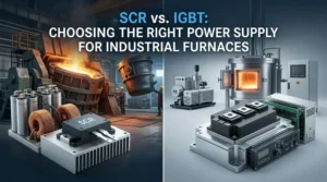
As the “heart” of the entire melting and heating system, the power cabinet of a medium-frequency induction furnace has witnessed a technological evolution from traditional thyristor (SCR) parallel resonance to modern IGBT series resonance (as well as dual-loop/PWM series resonance).
Below is a rigorous technical comparison and in-depth energy efficiency analysis of series and parallel resonant power supply lines.
I. Core Operating Principles and Topological Differences
1. Parallel Resonant Power Supply (Current-Source Inverter)
- Topological Characteristics: The rectifier side typically adopts a fully-controlled or semi-controlled thyristor bridge, with a large smoothing reactor in series on the DC side (exhibiting current source characteristics). The inverter bridge consists of thyristors (SCRs), and the load (induction coil and compensation capacitors) is connected in parallel with the output terminals of the inverter.
- Operating Mechanism: The voltage at the load terminal approaches a sinusoidal wave, while the inverter bridge is fed with a constant DC current. The operating frequency of the tank circuit is determined by the inductance and capacitance of the load, typically operating in an inductive state slightly above the resonant frequency.
2. Series Resonant Power Supply (Voltage-Source Inverter)
- Topological Characteristics: It mostly adopts uncontrolled rectification (or PWM rectification) plus an intermediate DC filtering large capacitor (exhibiting voltage source characteristics). The inverter switching devices mostly use IGBTs (or Integrated Gate-Commutated Thyristors, IGCTs) with excellent high-frequency performance, and the load is connected in series with the capacitors.
- Operating Mechanism: The inverter outputs a square-wave voltage, which is filtered through the series resonant tank circuit to form a sinusoidal current across the load. Its operating frequency automatically tracks the load resonant frequency, achieving Zero Voltage Switching (ZVS) or quasi-Zero Current Switching (ZCS).
II. Core Performance Comparison
| Performance Dimension | Parallel Resonance (SCR + Current Source) | Series Resonance (IGBT + Voltage Source) |
| Main Switching Device | Thyristor (SCR), with relatively lower switching frequency (typically < 1 kHz to several kHz). | IGBT, with much higher switching frequencies (1 kHz up to tens of kHz). |
| Start-up Performance | Start-up is more complex, requiring strict sweep-frequency circuits. Start-up is difficult under low-load or no-load conditions, and the success rate is heavily influenced by the charge state. | Extremely strong soft-start capability, enabling unconditional direct start-up. No-load, full-load, cold furnace, and hot furnace conditions can all be easily started successfully in one go. |
| Grid-Side Power Factor | Varies drastically with power regulation during the melting process. Power factor is low at low power levels, requiring additional reactive power compensation devices. | High power factor throughout the entire process (> 0.95), with minimal grid pollution and low harmonic components. |
| Load Adaptability | High requirements for load impedance matching; frequent manual or automatic voltage/frequency adjustment is needed when load melting causes drastic inductance variations. | Wide load self-adaptability. As the charge transitions from block chunks to liquid and temperature rises alter resistivity, the system automatically and perfectly tracks the changes. |
| Device Voltage Stress & Safety | Inverter bridge components endure high voltage and heavy current impacts, carrying a relatively high risk of commutation failure (inverter crowbar/failure). | Features sound current-limiting and overcurrent protection mechanisms. IGBT switching losses are low, resulting in high system operational stability. |
III. In-Depth Analysis of Energy Efficiency and Comprehensive Economy
Under the current “Dual Carbon” goals, energy efficiency ratio is the decisive metric for evaluating medium-frequency power supplies. Series and parallel resonance exhibit fundamental differences in energy consumption:
1. Transformer and Grid-Side Losses
- Parallel Resonance: Because its grid-side power factor is relatively low during holding or low-power stages, it generates large reactive currents, leading to increased transformer losses, higher line losses, and potential penalties from the power supply bureau.
- Series Resonance: Utilizing a voltage source combined with high-frequency chopping or PWM rectification technology, the input power factor is consistently maintained at an extremely high level with minimal reactive losses, effectively reducing transformer capacity requirements and cable heating losses.
2. Inverter and Tank Circuit Losses
- Parallel Resonance: Massive resonant circulating currents flow through the tank circuit (reactive currents oscillating back and forth between capacitors and coils), and the large reactor itself possesses non-negligible copper and core losses.
- Series Resonance: High-frequency operation of IGBTs reduces the physical volume of magnetic components. Losses in the series resonant circuit are mainly concentrated in the equivalent series resistance of the capacitors and coils. However, due to the fast switching speeds and low tail currents of modern power electronic devices, the overall electrical conversion efficiency is typically 3% to 5% higher than traditional parallel systems.
3. Energy Consumption Performance (Per Ton of Metal)
In actual casting and melting workshops, a series resonant power supply paired with an optimized furnace lining geometry achieves faster melting speeds:
- Shortened power-on times reduce furnace wall heat dissipation losses (i.e., lowering the thermal conduction energy wasted over time).
- The comprehensive power consumption per ton of copper, steel, or molten iron achieves a significant reduction, yielding substantial electricity cost savings for continuous, high-volume production enterprises.
IV. Selection Strategies and Future Evolution Trends
- Applicable Scenarios for Parallel Resonance:
- High-power, ultra-large-capacity, low-frequency heavy-load special industrial applications (some traditional large-tonnage steel melting scenarios) where projects are extremely sensitive to initial investment costs and grid conditions are relatively lenient.
- Applicable Scenarios for Series Resonance (Mainstream Trend):
- Modern melting furnaces, holding furnaces, heating, and quenching equipment ranging from small-and-medium tonnages to large tonnages.
- Modern green factories with rigorous requirements for energy conservation, consumption reduction, automation levels, constant power output, and workshop grid harmonic mitigation.
Driven by continuous breakthroughs in power electronics technology, all-digital control series resonant power supplies based on IGBT/IGCT technology are gradually replacing traditional thyristor-based parallel systems, becoming the core technical pillar propelling the induction heating industry toward high efficiency, intelligence, and low-carbon transformation.