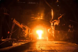
Due to its high efficiency, speed, and controllability, induction heating is widely used in applications such as metal heat treatment (e.g., quenching, tempering, annealing), welding, melting, and hot forging. In these processes, temperature is the most critical parameter determining the final product quality, including hardness, microstructure, and mechanical properties. Therefore, precise temperature measurement and control are essential.
Main Temperature Measurement Methods in Induction Heating
Not all temperature measurement methods are suitable for the unique high-frequency electromagnetic field environment of induction heating. The following are several mainstream technologies and their application characteristics.
1. Infrared Pyrometry
An infrared pyrometer is a non-contact temperature measurement device that determines an object’s temperature by measuring the infrared radiation energy emitted from its surface.
- Working Principle: Any object with a temperature above absolute zero emits electromagnetic waves (thermal radiation). The amount of this radiated energy and its wavelength distribution are closely related to the object’s surface temperature. The pyrometer’s optical system collects the energy radiated by the workpiece and focuses it onto a detector. The detector converts this energy into an electrical signal, which is then processed by an electronic circuit, corrected for a known emissivity value, and finally displayed as a temperature reading.
- Advantages in Induction Heating:
- Non-Contact Measurement: This is its primary advantage. It does not interfere with the induction heating’s electromagnetic field and is not subject to wear or damage from contact. It is ideal for measuring moving workpieces (like rotating shafts), inaccessible parts, or in extremely high-temperature applications.
- Fast Response Time: Infrared pyrometers can have response times in the millisecond range, enabling them to capture temperature changes in real-time during rapid heating processes like induction quenching.
- Wide Measurement Range: They can measure temperatures from a few hundred to several thousand degrees Celsius.
- Challenges and Countermeasures in Induction Heating:
- Emissivity: This is the main challenge for infrared thermometry. Emissivity represents an object’s ability to emit thermal radiation, with a value between 0 and 1. It is affected by the material type, surface roughness, level of oxidation, and even the temperature itself.
- Countermeasures:
- Choose a Two-Color (Dual-Wavelength) or Multi-Wavelength Pyrometer: Compared to single-color pyrometers, two-color models calculate temperature by measuring the ratio of radiated energy at two different wavelengths. This can, to a certain extent, negate the effects of changing emissivity, smoke, or water vapor.
- Calibration and Setup: In practice, it’s necessary to pre-determine the emissivity of a specific workpiece at the target temperature by comparing it with a contact thermometer (like a thermocouple) and then setting this value correctly in the pyrometer.
- Countermeasures:
- Environmental Interference: The induction coil, water vapor, and dust can partially obstruct the pyrometer’s line of sight, affecting measurement accuracy.
- Countermeasures: Keep the optical lens clean and use methods like air purges to clear the measurement path of obstructions. Design the installation position carefully to ensure a clear field of view.
- Emissivity: This is the main challenge for infrared thermometry. Emissivity represents an object’s ability to emit thermal radiation, with a value between 0 and 1. It is affected by the material type, surface roughness, level of oxidation, and even the temperature itself.
2. Thermocouple Thermometry
Thermocouples are the most common contact-type temperature sensors used in industry.
- Working Principle: Based on the Seebeck Effect. When two dissimilar conductors or semiconductors (A and B) are joined at two points to form a closed loop, a small voltage (thermoelectric EMF) is generated if the two junctions are at different temperatures. The magnitude of this voltage is related to the temperature difference between the junctions. By measuring this thermoelectric EMF and knowing the temperature of the cold junction (reference junction), the temperature of the measuring junction can be calculated.
- Advantages in Induction Heating:
- High Accuracy and Mature Technology: When not subjected to interference, thermocouples can provide very accurate and repeatable measurements.
- Lower Cost: Thermocouples are generally less expensive than high-performance infrared pyrometers.
- Unaffected by Emissivity: As a contact method, it directly measures the internal or surface temperature of the workpiece, independent of surface condition changes.
- Challenges and Countermeasures in Induction Heating:
- Electromagnetic Interference (EMI): This is the biggest obstacle for using thermocouples in induction heating. The high-frequency, strong magnetic field from the induction coil induces a significant interference voltage in the thermocouple wires. This induced voltage can be much larger than the weak thermoelectric signal, causing erratic or completely incorrect readings.
- Countermeasures:
- Shielding and Grounding: Use thermocouple cables with a metal shield and ensure the shield is properly grounded.
- Filtering: Add a low-pass filter at the instrument’s input to filter out high-frequency interference signals.
- Proper Wiring: Route the thermocouple leads as far away from the induction coil as possible and perpendicular to the power lines.
- Countermeasures:
- Physical Contact and Installation:
- It requires drilling a hole or spot-welding to attach the thermocouple, which can damage the workpiece and is not suitable for mass production.
- Using a thermocouple on a moving workpiece is very difficult.
- Response Time: The response time of a thermocouple is slower than that of a pyrometer because it needs time to reach thermal equilibrium with the workpiece.
- Lifespan: In high-temperature and rapid thermal cycling environments, thermocouples are prone to oxidation and damage.
- Electromagnetic Interference (EMI): This is the biggest obstacle for using thermocouples in induction heating. The high-frequency, strong magnetic field from the induction coil induces a significant interference voltage in the thermocouple wires. This induced voltage can be much larger than the weak thermoelectric signal, causing erratic or completely incorrect readings.
3. Fiber Optic Thermometry
This is a newer technology designed specifically for harsh environments like strong electromagnetic fields. It can be thought of as a special “thermocouple” that is highly resistant to interference.
- Working Principle: The probe tip is coated with a temperature-sensitive fluorescent or semiconductor material. A light pulse is sent through a fiber optic cable to the probe, exciting the material and causing it to produce fluorescence at a specific wavelength. The decay time or spectral characteristics of this fluorescence have a precise relationship with temperature. By measuring the returned optical signal, the temperature can be accurately determined.
- Advantages in Induction Heating:
- Complete Immunity to EMI: The entire sensing and signal transmission process is based on light, making it completely immune to electromagnetic fields, which is its core advantage.
- High Accuracy and Fast Response: It combines high precision with a relatively fast response time.
- Electrically Insulating: The probe and cable are both insulators, making it very safe.
- Challenges:
- High Cost: Currently, fiber optic thermometry systems are significantly more expensive than thermocouples and standard infrared pyrometers.
- Fragile Probe: The fiber optic probe is relatively delicate and requires careful installation.
How a Closed-Loop Temperature Control System Ensures Heating Accuracy
Regardless of the measurement method chosen, it is only the “eyes” of the system. To achieve precise temperature control, it must be integrated into a closed-loop control system.
A Closed-Loop Temperature Control System is an automatic feedback control system whose goal is to keep the actual temperature of the workpiece (Process Variable) closely following a pre-set desired temperature (Setpoint).
The system consists of the following main components:
- Temperature Sensor:
- Role: The “eyes” of the system.
- Function: To continuously measure the current temperature of the workpiece. This can be an infrared pyrometer, thermocouple, or fiber optic thermometer as discussed above.
- Temperature Controller:
- Role: The “brain” of the system, typically a PID controller (Proportional-Integral-Derivative).
- Function: a. Receives the actual temperature signal from the sensor. b. Compares it to the user-defined target temperature (setpoint) to calculate the Error (Error = Setpoint – Actual Temperature). c. Based on the error, it calculates a corrected output signal using the PID algorithm.
- Proportional (P): Reacts based on the size of the current error. The larger the error, the larger the output adjustment.
- Integral (I): Eliminates steady-state error. If the temperature remains below the setpoint for a period, the integral term accumulates, increasing the output power until the error is eliminated.
- Derivative (D): Predicts future error trends. If the temperature is rising too quickly, the derivative term will act to reduce the output in advance, preventing temperature Overshoot.
- Actuator:
- Role: The “hands” of the system.
- Function: In induction heating, the actuator is the Induction Power Supply. It receives the command signal from the controller (typically a 0-10V voltage or 4-20mA current signal) and adjusts its output power accordingly.
- Process:
- Role: The object to be heated.
- Function: The workpiece itself. Its temperature changes in response to the power output of the induction power supply.
Workflow to Ensure Accuracy:
- Set: The user sets a target temperature on the controller, for example, 850circC.
- Measure: The infrared pyrometer measures the current workpiece temperature, for example, 30circC.
- Compare: The controller calculates the error: Error=850−30=820circC.
- Control: Due to the large error, the PID controller sends a maximum (or near-maximum) output signal to the induction power supply.
- Execute: The power supply operates at full power, rapidly heating the workpiece.
- Feedback and Adjust:
- As the workpiece temperature rises rapidly (e.g., to 830circC), the error decreases (Error=20circC). The P (Proportional) action reduces the output power. Simultaneously, the D (Derivative) action detects the rapid rate of temperature rise and intervenes early, further reducing power to prevent the temperature from overshooting 850circC.
- If the temperature stabilizes at, for instance, 848circC, a small steady-state error exists. The I (Integral) action will slowly accumulate, gradually increasing the output power until the temperature is precisely stable at 850circC.
- Disturbance Compensation: If a sudden draft of cold air cools the workpiece, the system immediately detects the new error and quickly increases power to compensate for the heat loss, bringing the temperature back to 850circC.
Through this continuous, dynamic feedback loop of “Measure -> Compare -> Calculate -> Adjust,” the closed-loop system can overcome various disturbances (like power grid fluctuations, ambient temperature changes, or variations in initial workpiece placement), ensuring that the heating process temperature profile is accurate, stable, and repeatable.
Conclusion
- Sensor Selection: In induction heating, the infrared pyrometer is the mainstream choice due to its non-contact nature and fast response, but the issue of emissivity must be properly managed. The thermocouple still has value in R&D, one-off applications, or where interference is low, but EMI must be effectively countered. Fiber optic thermometry is a high-performance but costly solution.
- The Control System is Key: Simply having a good sensor is not enough. A well-tuned PID closed-loop temperature control system is the core component for achieving high-precision, high-consistency induction heating. It organically integrates the sensor, controller, and induction power supply to enable intelligent, automated, and precise management of the heating process.


